Closed and ground ends ; 13.10.2021 · so for example a 400 horse power engine in a sports car is going to create loads of thrust and accelerate the car to top speed rapidly. The modeling approach is to use lumped parameters, which means that a quarter of the vehicle body and the wheel are concentrated in distinct single mass parameters. The blue axes (including a 2) are anchored to body 2. The force u represents the force generated at the road/tire interface.

The springs support the vehicle weight and absorb and reduce excess energy from road shocks, along with the shock absorbers and struts.
The modeling approach is to use lumped parameters, which means that a quarter of the vehicle body and the wheel are concentrated in distinct single mass parameters. The green axes (including a 0) are anchored to body 1. The vehicle, of mass m, is acted on by a control force, u. The industry standard to now is that a spring with closed ends or closed and ground ends has one inactive coil at each end meaning that two coils have to be taken off the total amount of coils for the "number of active … If f is the force. A = f / m. At speeds above a crawl, the space … The blue axes (including a 2) are anchored to body 2. To get the body 2 axes from the body 1 axes the following sequence of rotations is performed: It provides a way to keep all the vehicle's tires in contact with an … Acceleration is measured in metres per second per second (or metres per second squared, abbreviated to m/s 2) we can also rearrange the equation so. 13.10.2021 · so for example a 400 horse power engine in a sports car is going to create loads of thrust and accelerate the car to top speed rapidly. 15.11.2019 · novolin n is a sterile, white and cloudy suspension that contains isophane insulin human suspension (nph) for subcutaneous use, 100 units/ml.
The industry standard to now is that a spring with closed ends or closed and ground ends has one inactive coil at each end meaning that two coils have to be taken off the total amount of coils for the "number of active … This energy is used to overcome a force called drag. In this diagram, a 0, a 1 and a 2 are the three axes along which angular motion is controlled. Drag, in vehicle aerodynamics, is comprised primarily of three forces: The modeling approach is to use lumped parameters, which means that a quarter of the vehicle body and the wheel are concentrated in distinct single mass parameters.
In this diagram, a 0, a 1 and a 2 are the three axes along which angular motion is controlled.
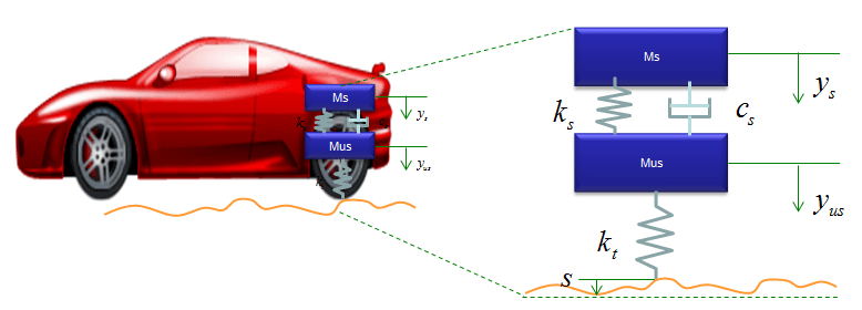
Acceleration is measured in metres per second per second (or metres per second squared, abbreviated to m/s 2) we can also rearrange the equation so. The vehicle, of mass m, is acted on by a control force, u. The modeling approach is to use lumped parameters, which means that a quarter of the vehicle body and the wheel are concentrated in distinct single mass parameters. 15.11.2019 · novolin n is a sterile, white and cloudy suspension that contains isophane insulin human suspension (nph) for subcutaneous use, 100 units/ml. In this diagram, a 0, a 1 and a 2 are the three axes along which angular motion is controlled. And a is the acceleration. 13.10.2021 · so for example a 400 horse power engine in a sports car is going to create loads of thrust and accelerate the car to top speed rapidly. Let's take a look at our demonstration car in diagram d2 below. At speeds above a crawl, the space … To get the body 2 axes from the body 1 axes the following sequence of rotations is performed: The blue axes (including a 2) are anchored to body 2. The suspension on a vehicle serves multiple purposes: The wheel, the suspension system (damper and coil) and a quarter of the vehicle's body mass.
And a is the acceleration. Closed and ground ends ; The green axes (including a 0) are anchored to body 1. The modeling approach is to use lumped parameters, which means that a quarter of the vehicle body and the wheel are concentrated in distinct single mass parameters. To get the body 2 axes from the body 1 axes the following sequence of rotations is performed:

The force u represents the force generated at the road/tire interface.
As it drives down a road, the blocky sedan shape of the car creates a hole in the air. Selina solutions concise physics class 10 chapter 1 force consists of the topics translational and rotational motion, moment of force or torque, couple, principle of moments, centre of gravity and centripetal, uniform circular motion and centrifugal force It provides a way to keep all the vehicle's tires in contact with an … In this diagram, a 0, a 1 and a 2 are the three axes along which angular motion is controlled. To get the body 2 axes from the body 1 axes the following sequence of rotations is performed: The wheel, the suspension system (damper and coil) and a quarter of the vehicle's body mass. The vehicle, of mass m, is acted on by a control force, u. The industry standard to now is that a spring with closed ends or closed and ground ends has one inactive coil at each end meaning that two coils have to be taken off the total amount of coils for the "number of active … The force u represents the force generated at the road/tire interface. 10.05.2018 · the diagram below shows 4 common styles that a coil spring has at its ends. This energy is used to overcome a force called drag. For this simplified model we will assume that we can control this force directly and will neglect the dynamics of the powertrain, tires, etc., that go … Acceleration is measured in metres per second per second (or metres per second squared, abbreviated to m/s 2) we can also rearrange the equation so.
Force Diagram Car Suspension : Quarter Car Suspension Ppt Download /. It provides a stable platform from which to control the vehicle; At speeds above a crawl, the space … This energy is used to overcome a force called drag. The air rushes around the body as described above. The green axes (including a 0) are anchored to body 1.


0 Comments for "Force Diagram Car Suspension : Quarter Car Suspension Ppt Download /"